
October 2025 Blog
Our first official month has wrapped up, and the team has already made great progress in car development. The month began with an exciting decision, UNB Formula Racing will produce an electric FSAE car. This opportunity was introduced by our new faculty advisor, Dr. Yukun Lu.
Dr. Lu recently joined the UNB Mechanical Engineering faculty and has already proven to be a tremendous asset to the team. She brings valuable experience from her previous work with industry-leading automotive companies, providing guidance and insight that have strengthened our development process.
Each member continues to embody what it means to be part of UNB Formula Racing. Dedicated, ambitious, and eager to take on new challenges regardless of prior experience. The energy and enthusiasm across the team have set a strong tone for the season ahead.
The team has also acquired a Solidworks sponsorship! This 3D modeling software will allow team members to model all the design concepts that they have been researching over the past month.
As always, new members are welcome to attend our weekly Saturday morning meetings. The team is on pace for success, and we encourage all students, no matter their faculty or experience level, to be a part of this exciting journey.
The Powertrain Team
This month, the powertrain team made some significant decisions. The team decided to switch to an electric vehicle (EV), moving away from the initial plan of building an internal combustion engine (ICE) car.
The first major decision for the EV vehicle is to use a single electric motor with a differential, rather than two motors and a split axle. This approach aligns with the team’s goal of building a reliable and simple car. The next key decision will be selecting the model of our motor.
Additionally, the Powertrain team was reorganized into three sub-teams: Drivetrain, Low-Voltage System, and High-Voltage System. Each sub-team was further divided into smaller groups, with a project lead responsible for each group.
Low-Voltage Sub-Team: Shutdown circuit, Vehicle Control Unit (VCU), and sensors/wiring harness
High-Voltage Sub-Team: Motor control and the tractive system
These changes aim to streamline development, improve communication, and ensure that each component of the powertrain is managed efficiently.
The Chassis Team
This month, the Chassis Team continued refining the frame’s geometry and dimensions to ensure compliance with competition rules while meeting the needs of other subteams. Adjustments have also been made to accommodate an electric motor rather than a traditional combustion engine.
The team has begun work on ergonomics, focusing on components such as the seat and harness. Efforts are underway to determine the most effective methods for mounting these parts to the frame safely and efficiently.
A steering system is also in development. Members have been exploring various mechanisms capable of turning the vehicle’s wheels and have started creating early CAD models.
After careful consideration, the team has chosen 4130 Chromoly steel as the tubing material for the frame. This alloy is commonly used in the automotive industry and offers the strength and performance characteristics best suited to the team’s needs.
Additionally, members are evaluating foam and honeycomb structures for the impact attenuator, a critical safety component designed to protect the driver in the event of a collision. The team continues to approach this task with great care and attention to detail.
The Dynamics Team
This month, the Dynamics team has made significant progress in both analytical modeling and suspension design.
One of our key developments was the creation of a MATLAB script to calculate individual wheel loads during braking, acceleration, and cornering. The algorithm uses vehicle parameters such as sprung and unsprung mass, location of center of gravity, motion ratios, coilover and tire spring rates, and roll-center heights. The model breaks down weight transfer into longitudinal, elastic (spring/roll stiffness), and geometric components, and outputs results including ride frequencies, wheel load distribution, roll stiffness, and roll gradient.
Since the calculations are linked to motion ratio and spring rate inputs, this tool allows us to quickly visualize how adjusting parameters affects ride frequency targets, roll balance, and front-to-rear weight transfer. The next step will be to integrate damping effects to study transient responses and eventually expand the tool into a full-vehicle Simulink model.
In parallel, we have been conducting research into rear suspension geometry, identifying target values and design assumptions for parameters such as rear roll center height (RCH), static camber, and anti-geometry (anti-squat, anti-lift), etc. The dynamics team has also been designing 2D side-view geometries for both front and rear suspensions. Our focus now will be on modeling and analyzing these parameters to refine them further.
The front suspension has made great progress. CAD models for the wheel hubs, uprights, and control arms are nearly finalized, as we continue to optimize our suspension geometry and develop the pushrod assembly. We’ve been iterating these designs to improve strength, reduce weight, improve ease-of-manufacturing, and overall packaging. Some of the major next steps include finalizing and integrating the steering and braking system.
Figure 1 below shows the front wheel hub sub-assembly. The rotors are a floating type (commonly seen in motorcycles), which allows them to maintain alignment and reduce warping.
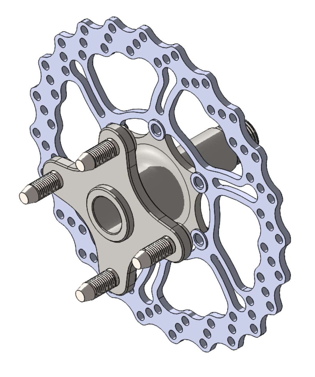
Figure 1
Figure 2 shows a simplified front-corner sub-assembly, which includes the wheel, upright, control arms, and pushrod.

Figure 2